3D Model 05: 3D-Printable Hypocycloid Speed Reducer Model
Introduction
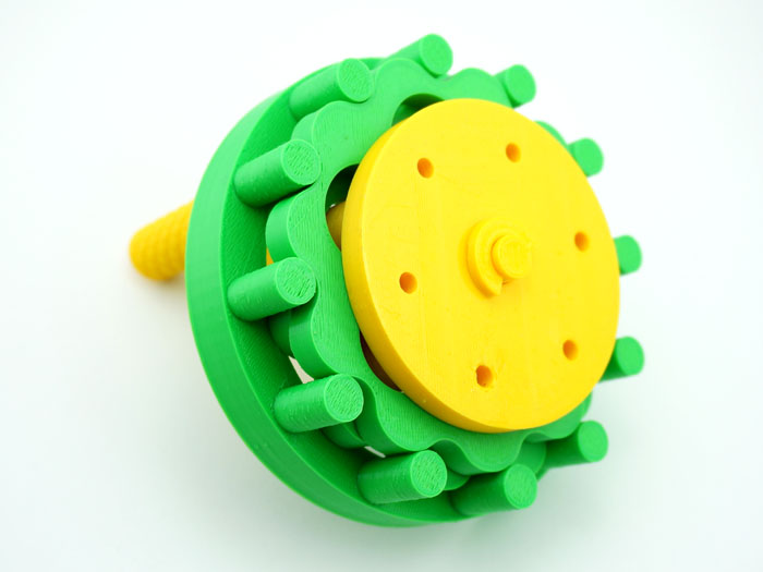
This is a fully functional hand-cranked 3D-printable model of the hypocycloid drive. We have tried to make this model as "skeletal" as possible to allow the inner workings of this truly remarkable mechanism to be clearly seen.
Download
Additional Notes
Hardware:
4 Metric Phillips-head M3x12 screws
Assembly Instructions:
- Insert the flat end of shaft into baseshaft, and insert baseshaft into handle. Make sure the holes in all three parts are aligned. Secure with two Phillips-head M3-12 screws.
- Insert conical end of shaft into ring from the bottom.
- Mount cam onto shaft, align it with the bottom hole on shaft, secure with a screw.
- Mount disk over cam.
- Mount the 2nd cam onto shaft, align it with the top hole on shaft, orient 180° relative to the 1st cam. Secure with a screw.
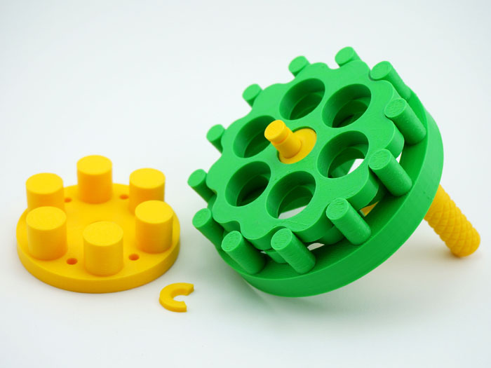
- Mount the 2nd disk over the 2nd cam. See picture below for the correct positions of the two disks relative to each other.
- Install output by inserting its pins into the disks' radial holes. Secure with washer.