3D Model 08: 3D-Printable Walking Gear Bot
Introduction
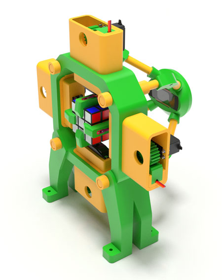
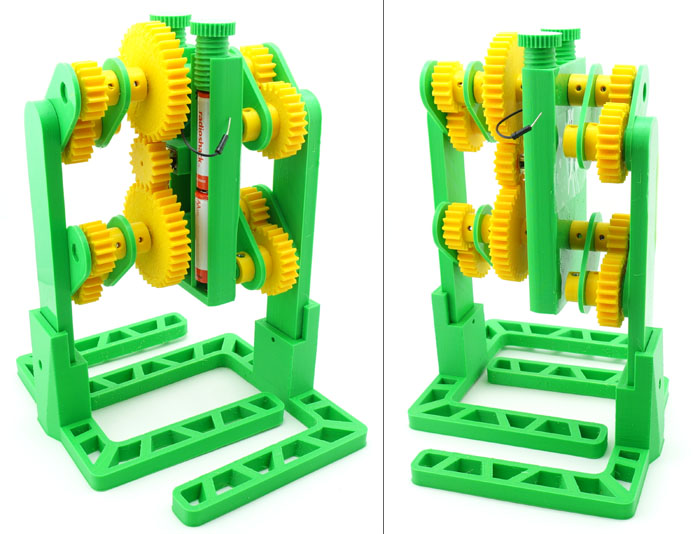
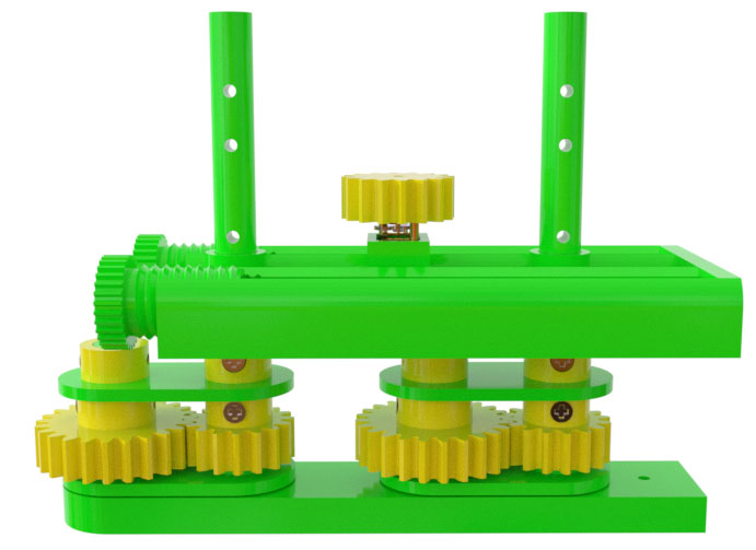
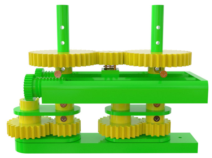
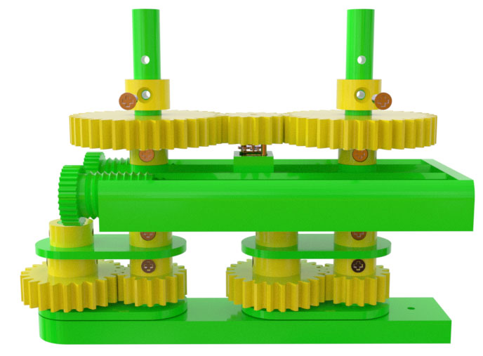
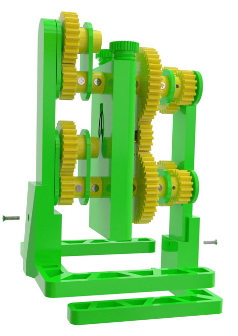
This is a motor-driven walking mechanism built around a bunch of meshing involute gears which convert simple rotation to a walking motion. This Walking Gear Bot is a bit wobbly and sluggish, but great fun to play with nonetheless, and very educational. See the video below to watch it trudge forward.
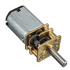
This Bot requires a 6V electric motor equipped with a speed reducer (available for less than $5 on eBay), four AA batteries, a paperclip and a couple of jumper cables or wires. And a small bag of screws, of course. No soldering required!
Download
Additional Notes
List of 3D-Printed Parts:
Hardware:
Watch the Walking Gear Bot make its way forward, one step at a time:
Assembly Instructions:
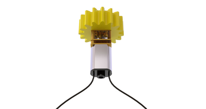
Step 1. Press pinion onto the motor's shaft all the way down. Attach jumper cables or wires to the motor's terminals.
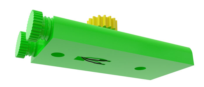
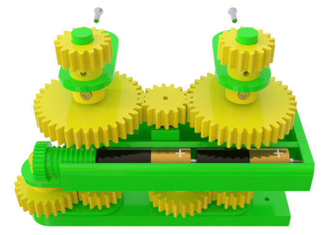
Step 2. Insert the motor into the slot in motorholder, let the wires come out of the two small holes in the bottom of the motor slot. Install two screws in the side of motorholder, secure them with two nuts on the inside. These two screws are electric conductors. They must be connected to each other with a conductive material. We used a short piece of copper wire but a simple office paperclip will work too. After installing the wire or paperclip, tighten the screws to keep the wire in place.
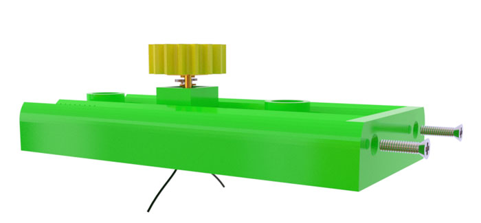
Step 3. Insert the loose ends of the wires into the square hole in the bottom of motorholder. The sections of the wires shown below in black must be flush with the bottom of the motorholder, otherwise they may interfere with the moving parts of the machine. We recommend securing them with a piece of Scotch tape.
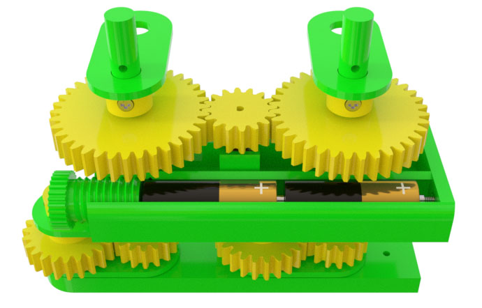
Install the four AA batteries, two in each chamber of the motorholder. Both batteries in one chamber must have their "plus" ends point in one direction, while both batteries in the other chamber must point in the opposite direction.
Secure the battery chambers with two thumbscrews. The purpose of these thumbscrews is to press the batteries to each other, to the conductor screws and to the loose ends of the motor wires tightly. Do not continue to Step 4 until you have tested the electric wiring: insert the loose ends of the wires between the battery ends and thumbscrews, tighten the thumbscrews, and make sure the motor spins.
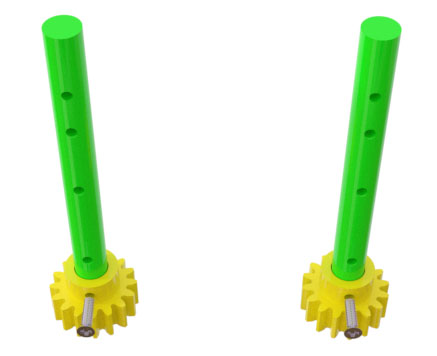
Step 4. Attach two gear16 wheels to the bottoms of two rods. Note that the holes in the rods are not symmetric. Attach the wheels to those ends of the rods that touched the platform of the 3D printer. Secure the wheels with screws.
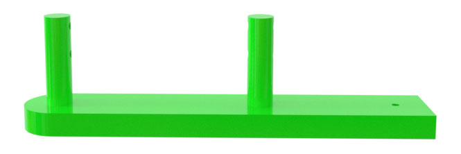
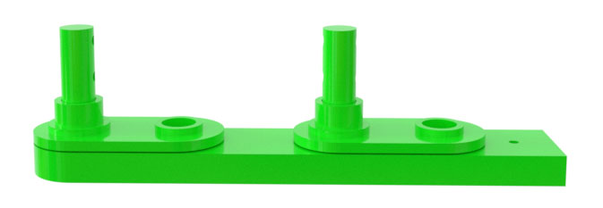
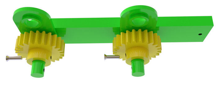
Step 5. Lay one of the two legs in front of you with the rounded end pointing to the left.
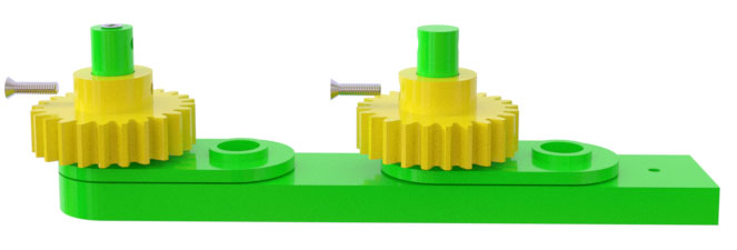
Step 6. Mount two bushings onto the leg's two axes as shown below.
Step 7. Mount two gear24 wheels onto the bushings, secure the wheels with screws.
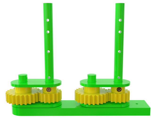
Step 8. Install the two rods with the gear16 wheels attached to them (assembled in Step 4) as shown below.

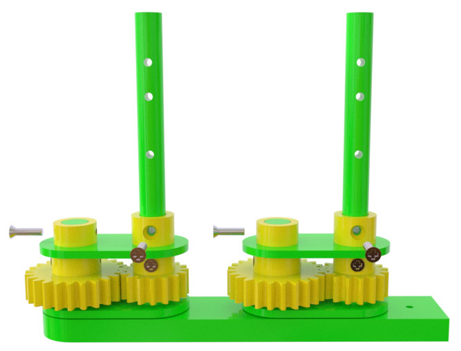
Step 9. Install two brackets.
Step 10. Mount two stoptube_short stop tubes over the gear24 wheels, and two stoptube_tall stop tubes over the gear16 wheels as shown below. Secure all four stop tubes with screws.
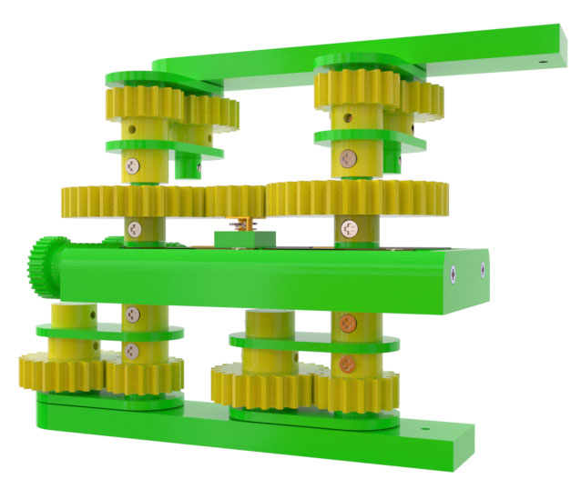
Step 11. Install motorholder with the motor, batteries and thumbscrews inserted.
Step 12. Mount two gear36 wheels onto the rods, secure with screws.
Step 13. Mount two stoptube_tall stop tubes onto the rods, secure with screws.
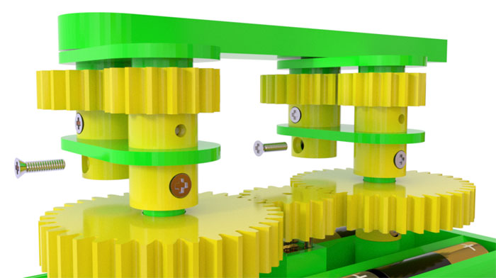
Step 14. Mount the 2nd pair of brackets onto the rods at 90° relative to the 1st pair of brackets.
Step 15. Mount the 2nd pair of gear16 wheels onto the rods, secure with screws.
Step 16. Using the 2nd leg, 2nd pair of bushings and 2nd pair of gear24 wheels, repeat Steps 5, 6 and 7 but install the bushings at 90° relative to the leg.
Step 17. Mount the 2nd leg with the bushings and wheels attached to it (assembled in Step 16) onto the main assembly by inserting the 2nd leg's axes into the brackets, and the rods into the 2nd pair of bushings.
Step 18. Install the last pair of stoptube_short stop tubes, secure with screws.
Step 19. Install the feet, secure with screws.
WARNING: Adult supervision is recommended. While in operation, keep away from little children as their fingers can be caught in the moving parts and cause minor injuries.