3D Model 11: 3D-Printable Screw Gear Model
Introduction
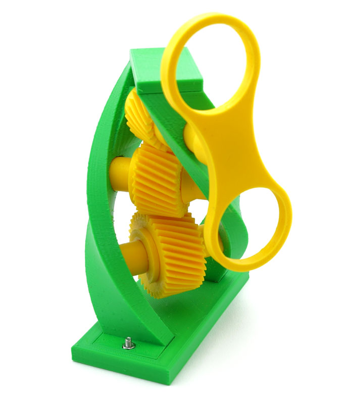
Our collection of 3D-printable gear mechanisms would be incomplete without the model of a screw gear drive. Screw gears are regular helical gears mounted on non-parallel, non-intersecting shafts. They are also known as crossed helical gears.
The shape of this screw gear drive was inspired by the DNA molecule. In this particular model, there are three gears mounted at 45° to each other, but the shaft angle can be any number between 0 and 90°. Our screw gear calculator allows you to model the outlines of two meshing screw gears in Blender instantly.
Download
Additional Notes
Hardware:
5 Metric Phillips-head M3x12 screws
2 Metric M3 nuts
Assembly Instructions:
- Mount bottom gear onto lower axis. Secure with washer.
- Mount middle gear onto the 2nd lower axis. Secure with washer.
- Insert the ends of the lower axes into the bottom and middle holes of stand.
- Mount stand onto base, secure with two screws and nuts.
- Insert the narrow end of upper axis into the top hole of one of the spirals from the outside, then into stop tube, top gear, and the other spiral's top hole. The top gear's narrow end must point away from the stop tube.
- Align the holes in the stop tube and top gear with the holes in the upper axis. Secure with two scres.
- Attach spinner to the upper axis, align holes, secure with a screw.