3D Model 15: 3D-Printable Mechanical Spinning Top
Introduction
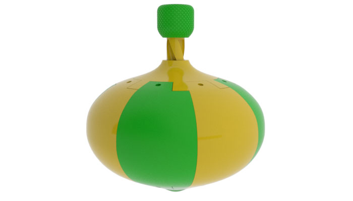
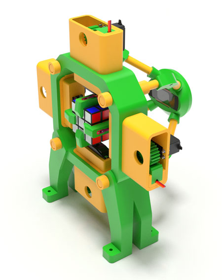
This fully 3D-printed mechanical spinning top is not only a fun toy, but quite educational too, and in more ways than one. Just like any spinning top, it demonstrates a fascinating physics phenomenon known as the gyroscopic effect, which prevents the toy from falling over while spinning. Also, nestled inside is a neat little mechanism which converts the reciprocal motion of the spiral rod to the one-way rotational motion of the spinning top's body. It is called the overrunning clutch, and we have managed to make it fully 3D-printed, even the torsion springs!
This fairly massive toy measures 20cm in its widest section, and not exactly a small project. However, the parts are designed in such a way that they are very easy to print and, with one exception, require almost no support. Assembly only takes minutes!

Introduction Video:
Download
Additional Notes
List of 3D-Printed Parts:
Hardware:
10 Metric Phillips-head countersunk M3x12 screws;
8 Metric M3 nuts;
48 US Penny or similar coin (optional).
Assembly Instructions
:Step 0 (Optional)
Insert US penny (or similar) coins in the inner grooves of the segments for additional weight and stability of the spinning top. Use 6 pennies per segments.
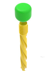
Step 1
Screw the handle onto the rod.
Step 2
Screw the tip into the bottom, put a thin metal object (such as an Allen key) through the hole in the tip to tighten.

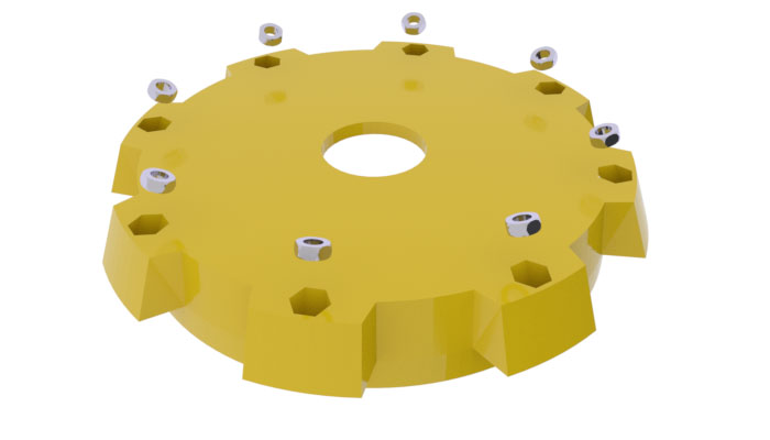
Step 3
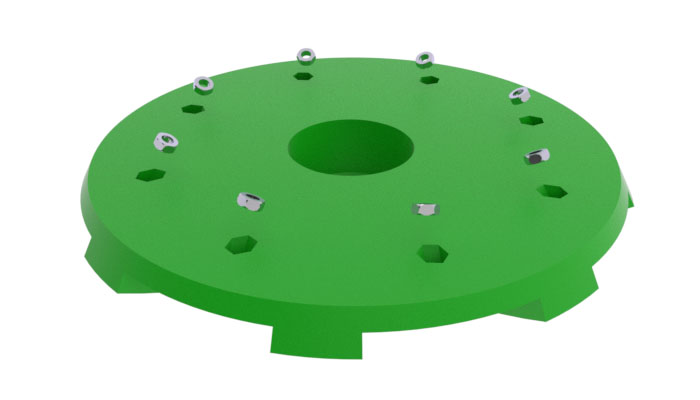
Insert the 8 M3 nuts into the hexagonal slots of the base. Secure them in place with wads such as balls of crumbled Bounty tissue.
 Step 4
Do the same with the bottom.
 Step 5
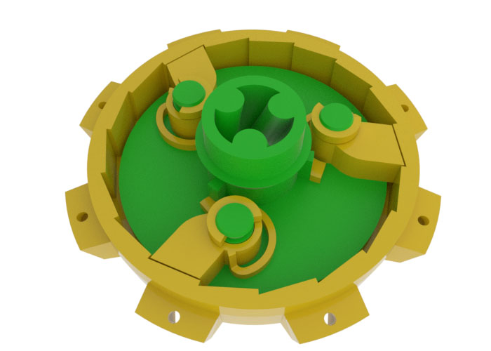
Assembly the overrunning clutch mechanism by putting the clutch inside the base, mounting the three pawls onto the pins of the clutch as shown here, and securing them with three retaining rings.
 Step 6
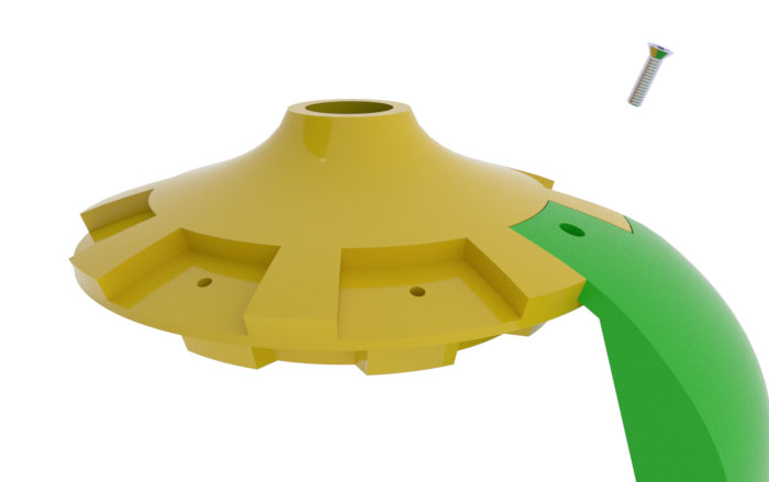
Hold together the top, base, and one of the segments. Align holes. Bind the three parts together tightly with an M3x12 screw.
Step 7
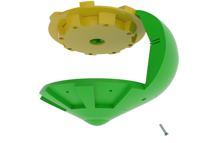
Attach the bottom to the bottom part of the segment, bind the two parts together tightly with an M3x12 screw.
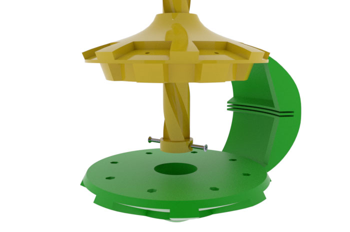
 Step 8
Insert the rod through the hole in the clutch. Attach the sleeve to the rod and secure it with two M3x12 screws.
 Step 9
Install the other 7 segments and secure them with two M3x12 screws each.