3D Model 10: 3D-Printable RC Tank
Introduction
- Prints without support!
- Assembles without hardware!
- Wires without soldering!
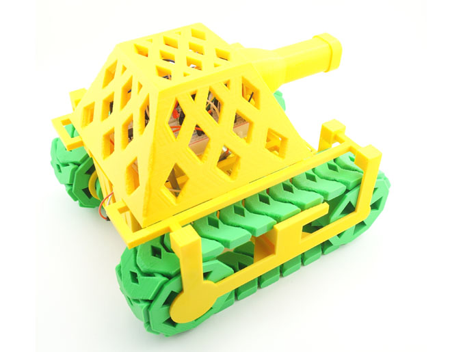
This RC tank does not require a single bolt or nut. You just print the parts, snap them together, connect the motors and electronics, and it is ready for battle. It shows excellent off-road capabilities, and turns on a dime. Each of this tank's two tracks is printed in a single piece, thus eliminating the need for assembly hardware.
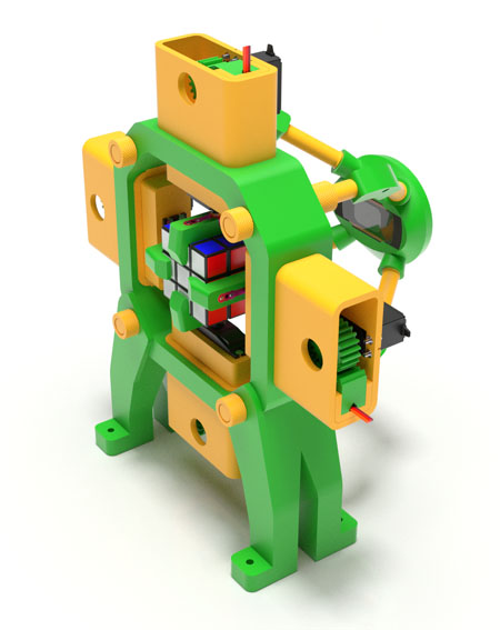
The machine shown in this video is powered with a Picaxe 20M2 microcontroller installed on a 300-hole mini-breadboard. There is also an H-bridge motor driver, an IR sensor, a couple of resistors and capacitors, and a whole bunch of jump cables. The entire set of electronic components used here can be bought on eBay for just a few dollars. The tank is operated with a regular Sony TV remote control.
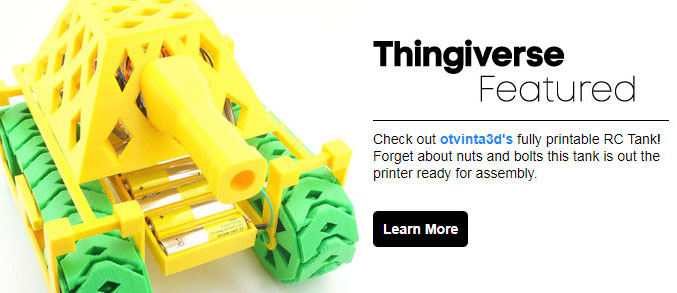
On July 17, 2017, this model was featured on Thingiverse!
Download
Additional Notes
List of 3D-Printed Parts:
The print time is approximate, based on the estimate provided by the Simplify3D software.
Total printed parts: 22
Total print time (approx.): 1,483 min. (24 hours and 43 min.)
Motors & Batteries:
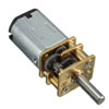
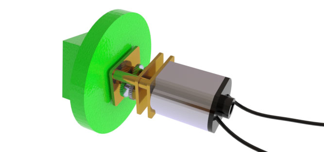
This tank uses two (2) DC 6V 30RPM Micro Speed Reduction Gear Motors shown here.
7 AA batteries are required: 3 to power the logic and 4 to run the motors.
Watch this tank in action:
Assembly Instructions:
Step 1:
Insert the motor shafts into adapters. Push all the way in. Attach wires to the motor terminals.
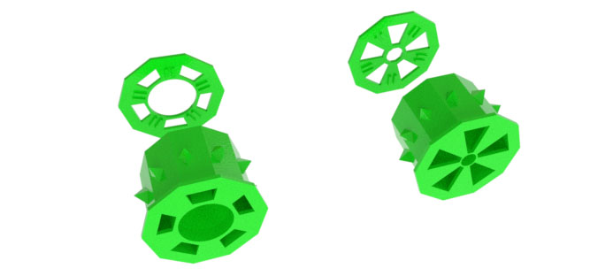
Step 2:
Snap the hubcaps onto their respective font and back wheels.
The wheel spokes go into the grooves of the hubcaps.
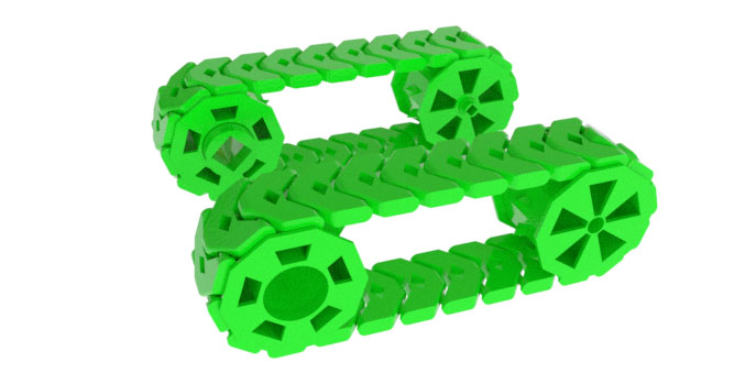
Step 3:
Install the tracks over the wheels as shown here.
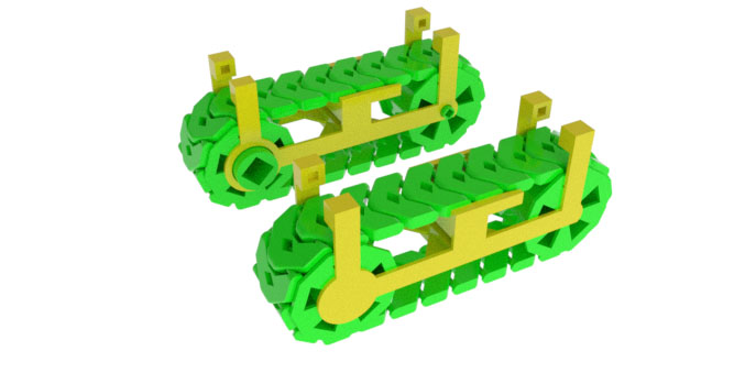
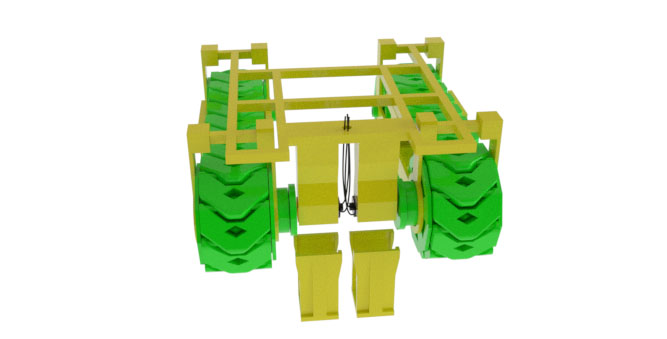
Step 4:
Snap together the inner and outer halves of the rails, with the wheels and tracks sandwiched in-between.
Step 5:
Mount the rails onto the frame. The square pegs of the frame go into the square holes in the rails.
Place the motors with the adapters attached to them into the motor chambers in the bottom of the frame, and insert the adapters into
the square holes of the front wheels. Secure the motors with motor holders.
Run the motor wires through the round hole in the frame.
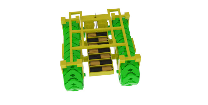
Step 6:
Prepare the battery holder. Line the sides of the battery box with conductive material such as foil. We are
using sticky copper foil tape, but regular aluminum foil with some glue can be used too.
Run the wires through the triangular holes in the sides of the battery holder.
There are two separate chambers: one for 3 AA batteries, and the other for 4 AA batteries. The former powers the microcontroller,
the latter the motors. Once everything is ready, mount the battery holder onto the rails as shown here.
Step 7:
Place the breadboard with the electronics on top of the frame, connect the motors and power.
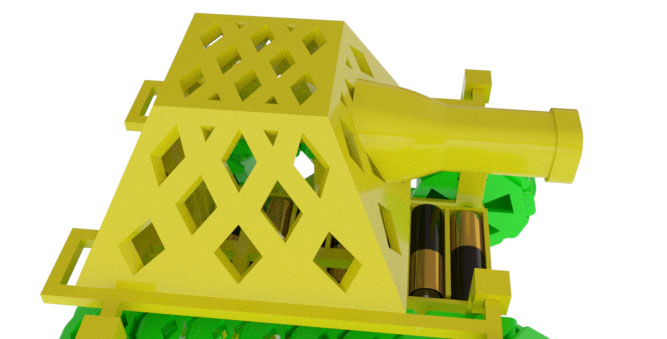
Install the cover. The double pegs on the sides of the cover must straddle the cross beams of the frame.
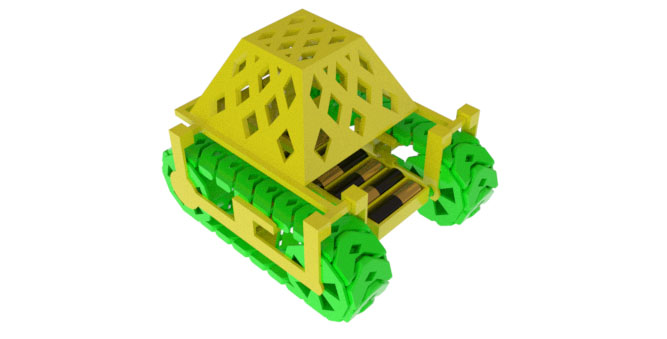
Step 8:
Install the cannon.
Electronics Instructions
The RC tank shown here uses the Picaxe 20M chip as its microcontroller, L293D H-bridge to provide bidirectional current for the motors, a standard infrared receiver (available, among other places, at the Picaxe store under the part number LED020), a 330Ω resistor and a 100nF ceramic capacitor. All these components are placed on a 300-hole mini-breadboard as shown below. A Sony TV remote is required to control this model.
Click on the image below to enlarge.
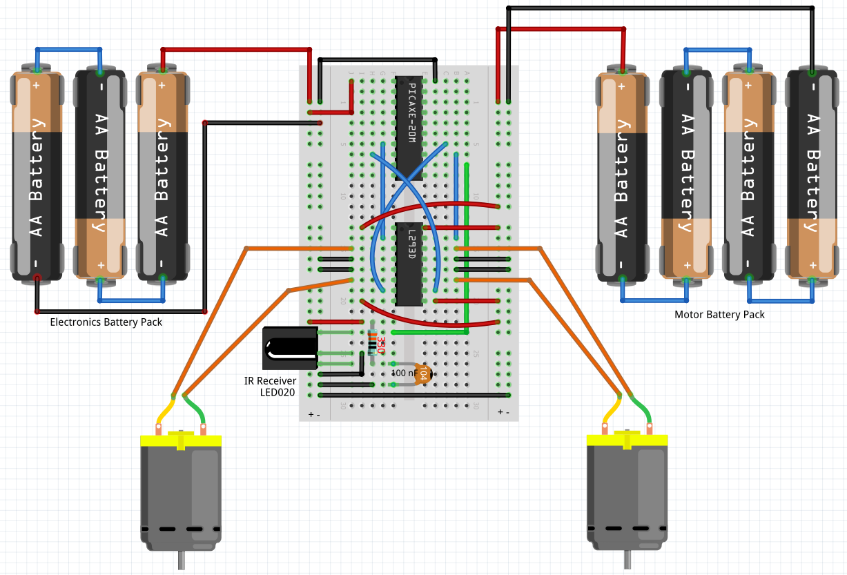
Explanation:
- The left power bus of the breadboard is for electronics and should be connected to the 3-battery pack (4.5v), and the right power bus is to power the motors and should be connected to the 4-battery pack (6v). The left and right ground buses should be connected with each other.
- The IR receiver needs to be placed on the breadboard with its "bulge" pointing to the left. Its bottom leg is connected to power (left bus) via the resistor, and to the ground via the capacitor. The middle leg is connected directly to the ground. The top leg is the data signal fed into Picaxe's B.6 input (pin 12).
- The Picaxe chip needs to be connected to power and ground (left bus) via pins 1 and 20, respectively, as shown on the diagram.
- The H-bridge is made up of two autonomous halves, left and right, controlling one motor each. Each half must be connected to power (right bus) via the outer pins 1, 8, 9 and 16, and to ground via the middle pins 4, 5, 12, and 13.
- The motors are connected to the H-bridge's pins adjacent to the ground pins. Motor 1 is connected to pins 3 and 6, and Motor 2 to pins 11 and 14.
- The H-bridge currents driving the motors are controlled via pins 2 and 7 (Motor 1) and pins 10 and 15 (Motor 2). Those pins must be connected to Picaxe's outputs C.3 and B.4 (pins 7 and 14) and C.2 and B.5 (pins 8 and 13), respectively.
-
The underlying Picaxe code is as follows:
do
irin b.6, b1if b1 = 116 then ' forward
high c.3
high c.2low b.4
low b.5
elseif b1 = 51 then ' right
high c.3
low c.2low b.4
high b.5
elseif b1 = 52 then ' left
low c.3
high c.2high b.4
low b.5
elseif b1 = 101 then ' stop
low c.3
low c.2low b.4
low b.5
elseif b1 = 117 then ' reverse
low c.3
low c.2high b.4
high b.5
endif
loop