3D Model 09: 3D-Printable Automotive Differential
Introduction
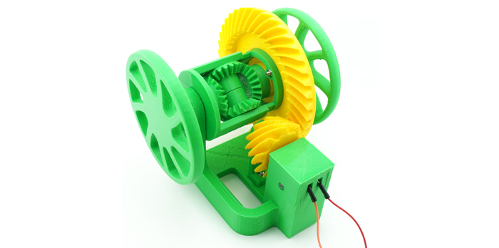
The automotive differential is something every automobile has: this ingenious mechanism transmits power from the driveshaft at 90° to the driving wheels, while allowing them to rotate at different speeds when the driving conditions call for it, such as during a turn.
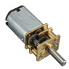
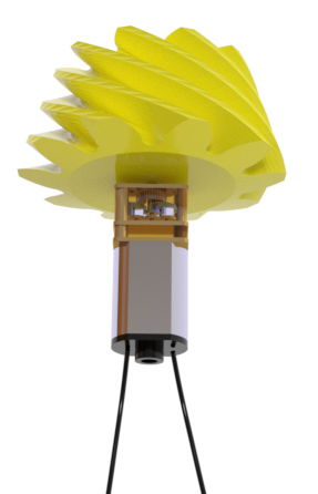
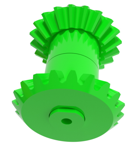
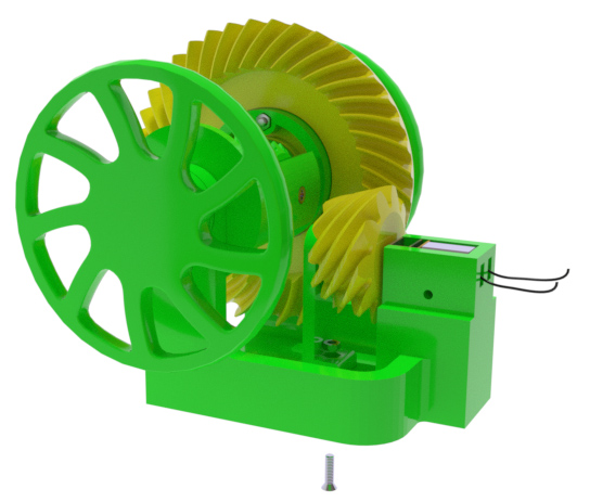
This is a motorized model of the most basic kind of automotive differentials, known as the open differential. Unlike most 3D-printable differential models out there, this one is equipped with a hypoid, not bevel, pinion/ring gear pair. The model is powered by a 6V electric motor equipped with a speed reducer.
Download
Additional Notes
List of 3D-Printed Parts:
Hardware:
Assembly Instructions:
Step 1:
Attach wires to the motor's terminals. Mount pinion onto the motor, press all the way down. Set it aside.
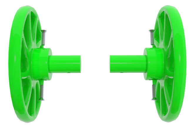
Step 2:
Mount the two wheels onto left_shaft and right_shaft. The slightly concave ends of the shafts must point away from the wheels. Secure with screws. Set those aside.
Step 3:
Mount the two spider gears onto spider_shaft. The toothed ends of the gears must point away from each other.
Step 4:
Mount the parts from Step 3 onto carrier. The flat sides of spider_shaft must fit the grooves on the innder sides of the carrier's well.
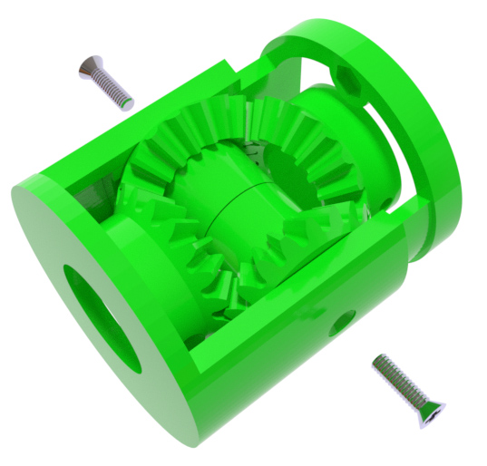
Step 5:
Insert the two side gears as shown below, install carrier_cover and secure with two screws.
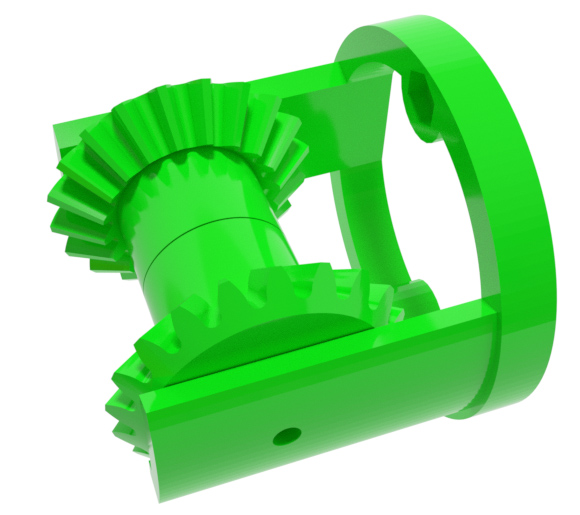
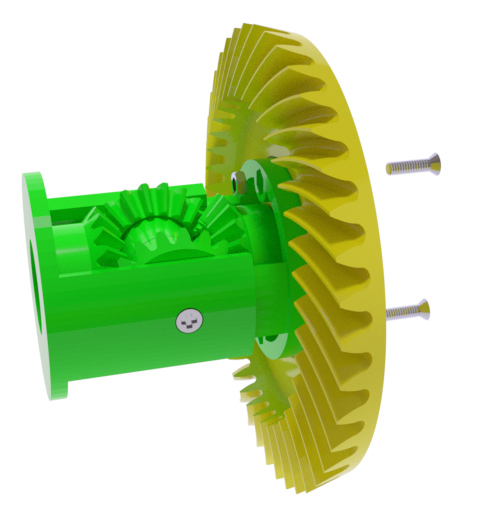
Step 6:
Attach the gear assembly from Step 5 to ring, secure with two screws and two nuts.
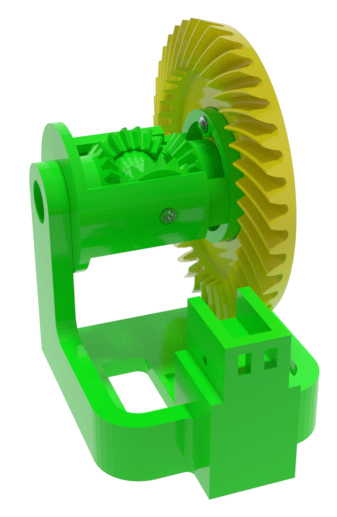
Step 7:
Mount the assembly from Step 6 onto stand.
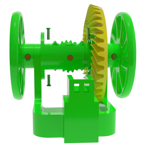
Step 8:
Insert wheel shafts into the side holes of the stand and into side gears. The longer shaft is inserted on the ring's side. Secure with two screws on each side.
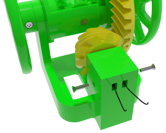
Step 9:
Install the motor with the pinion mounted on it. Insert the motor wires into small holes in the back of the motor chamber. The ring gear may need to be pushed aside gently to make room for the pinion as it is being installed. Also install arm, secure with a screw and nut.
Step 10:
Install motor_cover, secure with two screws.