3D Model 14: 3D-Printable Hyperboloidal Gear Model
Introduction
This huge clock (23" x 8") is sure to be an attention grabber and a great conversation piece in a crowd of computer and robotics nerds. And it shows precise time too!
Please watch this introduction video:
Download
3D-Printed Parts
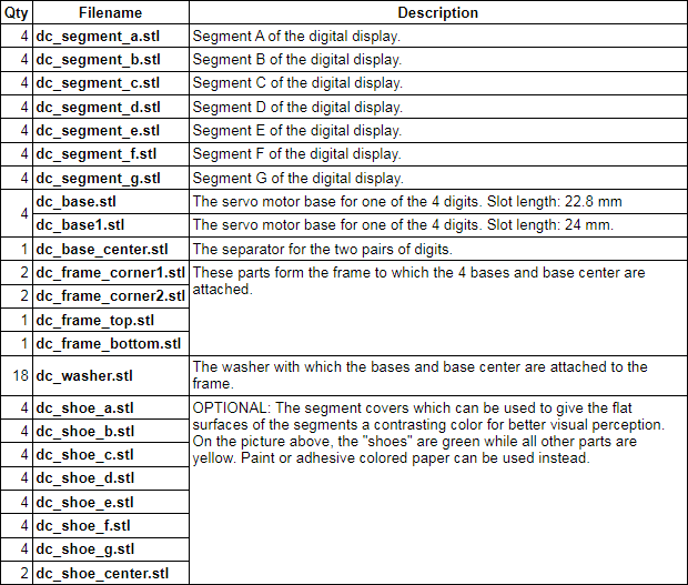
List of 3D-Printed Parts:
Hardware
- 28 servo motors SG90;
- 20 male-female servo extension cables, 15cm;
- 02 (or more) Pololu Maestro servo controllers, assembled (total number of pins should be at least 28);
- 02 (or more) 6 volt, 3 amp. power sources, one for each servo controller;
- 02 (or more) Balun adapters, one for each servo controller;
- 01 Raspberry PI 3;
- 12 metric M3-12 Phillips-head countersunk screws;
- 12 metric M3 nuts;
- 4 metric M2-12 Phillips-head countersunk screws to attach the Raspberry PI and servo controllers to the frame, and optionally, 28 more to secure servo motors in place.
Installation Instructions
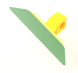 Give the flat surface of each of the segments, and also the two round center delimiters, a contrasting color for better visual perception.
Several options are available:
Give the flat surface of each of the segments, and also the two round center delimiters, a contrasting color for better visual perception.
Several options are available:
- Use a dual-extruder 3D printer if available.
- Use spray paint.
- Cut the outlines out of adhesive colored paper and paste them onto the flat surfaces of the segments. Cutout outlines in PDF format (US Letter and A4 sizes) can be downloaded from here.
-
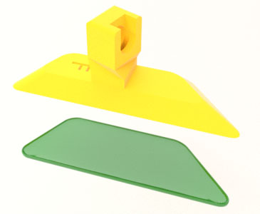
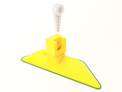
Attach the segment to its respective 3D-printed "shoe" with glue (we used this option for our model):
Step 2:
Insert the one-sided horn that comes with the SG90 servo motor into each segment. Make sure it is inserted all the way in. Clip the tip of the horn if necessary to ensure full insertion.
Step 3:
Using 12 M3-12 screws and 12 M3 nuts, assemble the 4 frame corners, frame top and frame bottom into a single frame.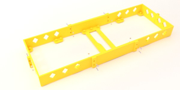
Step 4:
Mount the four bases and base center onto the frame. Secure with washers.
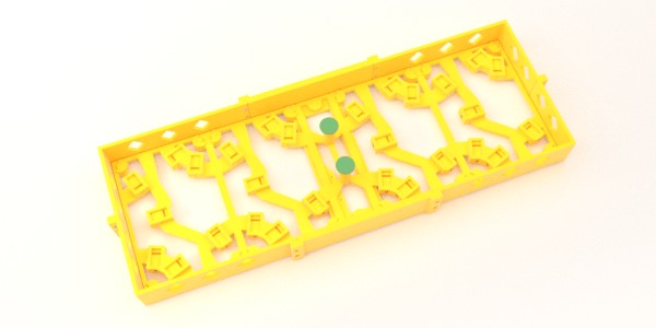

Step 5:
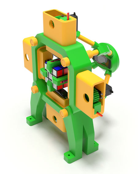
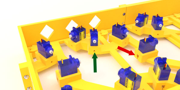
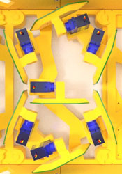
Insert the servo motors into their slots as shown on the image below. Run the servo cables through the slits marked by a red arrow. Optionally, secure the servos in place by screwing M2-12 screws into holes marked by a green arrow. Installing the segments onto the motors should be done during the calibration phase described below.
Connecting Electronics
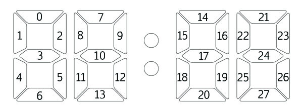
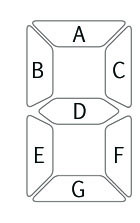
The servo controllers need to be attached to the back of the frame bottom with a single small screw each. An M2-12 screw can be used for that. The servo cables need to be connected to the pins of the servo controllers. The assignment of segments to the controllers' pins is arbitrary but you must carefully record which segment is assigned to which pin of which controller. The segments are numbered as follows:
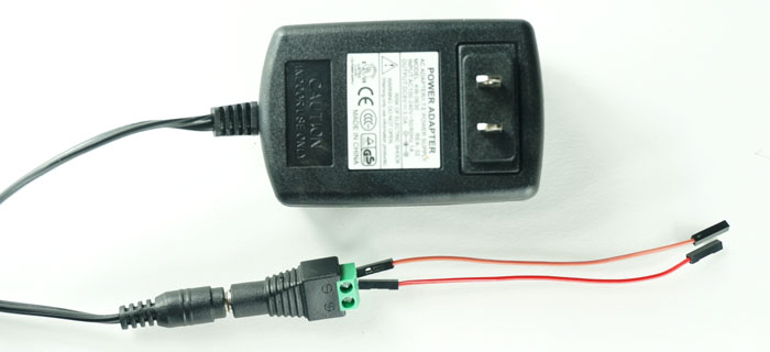
For the power supply for the Maestros, use 6V, 3A (3000 mA) wall chargers, one for each controller. We recommend connecting the charger to the controller with the help of a DC female "balun" adapter and two male/female jumper cables, as shown below. The male ends of the jumper cables are inserted in the holes of the balun adapter and secured with the tightening screws. The female ends are connected to the power pins of the Maestro.
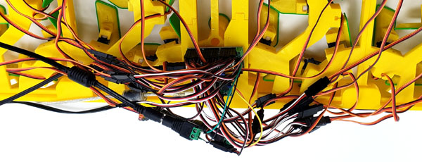
The photo below shows two Pololu Maestro controllers (24-channel and 12-channel) in their working positions, with the servo cables and power wires connected. In our implementation, the servos for segments 0 to 6 are connected to pins 0 to 6 of the 12-channel controller, and the servos for segments 7 to 27 are connected to pins 0 to 20 of the 24-channel controller.
The Raspberry PI can optionally be attached to the frame top with two small screws. The servo controllers eventually need to be plugged into the UBS ports of the Raspberry PI, but they temporarily need to be plugged into a PC for calibration.
Calibration
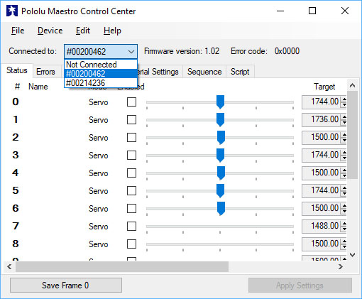
After firing up the Maestro Control Center, obtain the serial numbers of the controllers from the "Connected to" drop-down box. In our implementation, the 12-channel controller has the serial number #00200462, and the 24-channel controller #00214236. You will use these serial numbers when creating a data file mapping the segments to the servo controllers' pins.
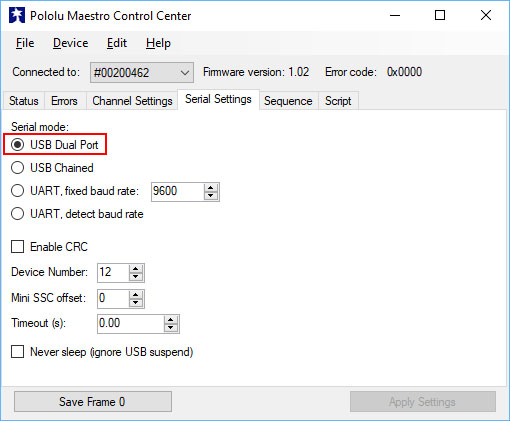
Go to the Serial Settings tab and select USB Dual Port for the serial mode. Then press Apply Settings. Make sure this is done for every one of your controllers.
Then return to the main Status tab to calibrate your servos. At this point, you need to attach the segments to the servos one after another, and using the Control Center's sliders, determine and record the "on" and "off" target settings for every servo.
Each segment is stamped with a letter A to G designating its position within the display, according to the following chart:
The two images below show all segments in the correct "on" and "off" positions, respectively:
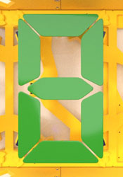 |  |
Once the "on" and "off" values for every servo are determined and recorded, they need to be placed in a text file under the name DigitalClock_Data.txt. Its format is described in the following section.
Software
The clock is driven by a Universal Windows Platform (UWP) application, called ServoClock, to be executed on Raspberry PI running Windows IoT. It is a background (also known as "headless") application with no user interface.
Please download the app from the link below:
7.2 App Installation on Raspberry PI
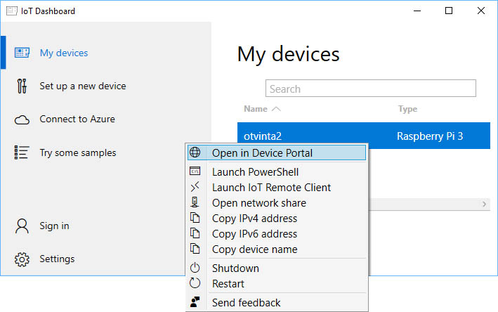
The following instructions assume that you have already downloaded and installed Windows 10 IoT Core Dashboard on your local PC, installed the Windows 10 IoT Core operating system on your Class-10 Micro SD card, booted your Raspberry PI from it, and connected the PI to your local network via WiFi and/or an Ethernet cable. Your Raspberry PI device should be showing in the My devices list of the IoT Dashboard:
To install the ServoClock app onto your PI, please follow these easy steps:
- Download the .zip archive for ServoClock from the link above. Unzip it to a temporary directory of your PC's hard drive, such as c:\tmp.
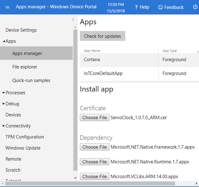
- In the IoT Dashboard, right-click on your device, and select Open in Device Portal. In the Windows Device Portal, go to Apps, Apps manager.
- Under Install app, for App package, select the file with the extension .appx in the temporary directory, and for Certificate, select the file with the extension .cer.
- Click on Add dependency three times. For the three Dependency boxes, select the three files in the \Dependencies\ARM subfolder of the temporary directory.
- Click on Go under Deploy.
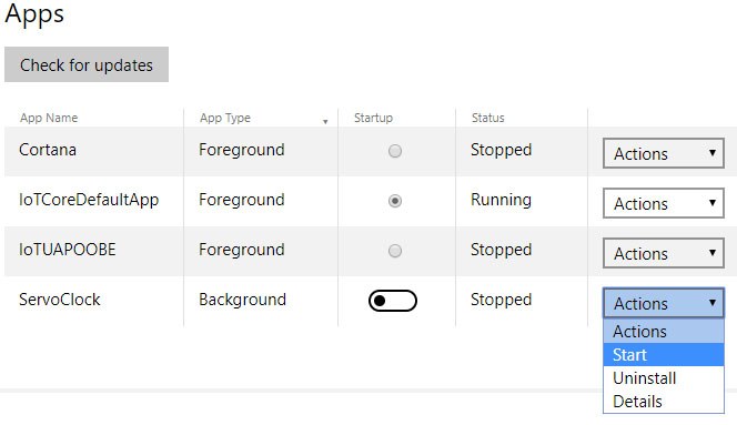
Now the app ServoClock should appear on the Apps list. You can start the application by choosing "Start" in the Actions drop-down box, and optionally mark it as startup by clicking on the radio button in the Startup column:
7.3 App Input Data Format
The application reads its input data from the text file DigitalClock_Data.txt, and writes its errors and other information to the text file DigitalClock_Log.txt located in the same folder. On Raspberry PI, the input file should be placed in the folder
The format of the input file is as follows:
- It is an ASCII file.
- Individual lines are separated with a CR/LF pair of characters (chr(13) & chr(10)).
- If a line begins with the '%' character, this line is a comment and its content is ignored by the app.
- A data line contains the following space- or tab-separated values: segment number, controller ID, pin number, "on" target value, and "off" target value.
- A segment number is a number between 0 and 27. Segments may appear in any order within the file, but all 28 segments must be present, and duplicates are not allowed. See Section 5 for the segment numbering chart.
- A controller ID must be pre-pended with a # character, such as #00214236.
- Empty lines are allowed for better readability.
- If a line starts with the '$' character, it is a configuration parameter. Currently only one parameter is supported: $hours. The line $hours 24 makes the clock display time in a 24-hour system, while any number other than 24, or no $hours parameter at all, makes the clock use the 12-hour system.
Please download a sample DigitalClock_Data.txt file here.