TUTORIALS |
|
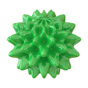
3D surfaces can be defined parametrically, with three functions x(u, v), y(u, v) and z(u, v). While the parametric equations of simple
surfaces such as a cylinder or sphere can be easily derived with just a pencil and paper, others, such as a spinning hypocycloid orbiting around a center
which itself is rotating, seem impossibly complex.
This tutorial provides a system and method for deriving the equations of even the most complex of 3D surfaces using the multiplication
of transformation matrices based on an online calculator we have developed.
Updated 2023-04-12
|
|
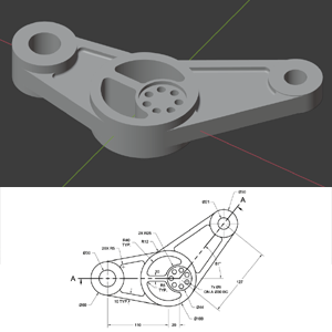
This tutorial explains how to model a tricky part based on a technical drawing in Blender 2.9.
The drawing, which we downloaded from GrabCad.com, poses a number of challenges.
Specifically, it contains multiple joints between straight and cylindrical surfaces,
as well as cylindrical and other cylindrical surfaces.
The tutorial begins with the solving of two geometry problems necessary to model this part,
and then proceeds with the actual modeling, which is not a quick undertaking. We had to time-lapse some portions of
the modeling process to prevent the video from being overly long.
Updated 2020-10-25
|
|
This tutorial briefly explains the math behind non-circular gears, and demonstrates how to quickly design and test a pair of
meshing non-circular gears in Blender 2.81 (earlier versions of Blender can be used too.)
The math is not exactly trivial,
but we have developed an online calculator which completely shields you from all the intricacies of non-circular formulas.
You do need to come up with an equation in polar coordinates for the first gear's pitch curve, and the calculator
will generate the toothed outlines for both gears automatically. With the help of this calculator, you can design your own pair of unique,
amazing and fully functional non-circular gears in minutes!
Updated 2020-01-14
|
|
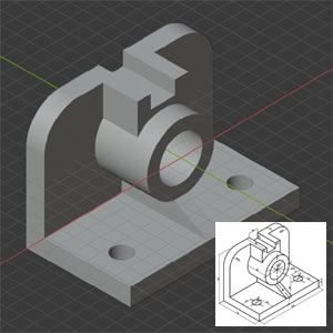
In this tutorial, you will learn how to model a 3D-printable part based on a technical drawing.
Specifically, it focuses on how to couple cylindrical and flat surfaces,
and also drill round through holes, without the use of the Boolean modifier.
The tutorial also demonstrates how to test a model for flaws from a 3D-printing point of view.
Updated 2019-12-23
|
|
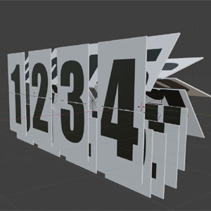
In this tutorial, you will learn how to model and animate a cool-looking old-fashioned split-flap display in Blender.
A split-flap display is a great way to spice up any video requiring an eye-catching timeline indicator.
In a split-flap display, there are flaps attached via hinges to a rotating shaft. Each flap contains the picture of the top or bottom half of a
digit or word on each side. Two adjacent vertically oriented flaps at the front of the display form a full digit or word.
In Blender, the movement of the flaps can be animated using drivers. The driver formulas are not exactly trivial,
but thanks to the online calculator we developed, all you need to do is copy and paste them from the calculator to Blender.
Updated 2019-12-15
|
|
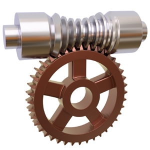
This Blender 2.8 tutorial takes advantage of our newest Instant Throated Worm Calculator which takes the
worm drive dimensions as the input, and calculates a worm-generating Python script as the output.
Unlike our original throated worm calculator, this one requires a single copy-and-paste operation per worm
and very little post-processing.
Updated 2019-10-29
|
|
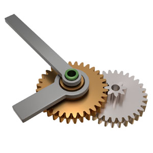
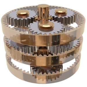
This Blender 2.8 tutorial explains how to design a simple 2-stage gear train with coaxial input and output
shafts and given gear ratio (1:12 in this example.) The resultant mechanism can be used as a toy clock with the minute
hand attached to the input shaft and hour hand to the output shaft.
The tutorial uses a short Python script to compute the number of teeth for each of the gears involved. It also demonstrates how to
turn a gear with a low number of teeth and profile shift to a solid object without
creating overlapping faces.
Updated 2019-04-20
|
|
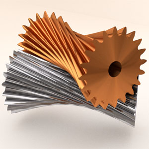
Hyperboloidal gears are essentially regular spur gears with their top and bottom twisted
in the opposite directions. A hyperboloidal gear's reference surface is a hyperboloid, which is a surface
obtained from a regular cylinder by twisting its top and bottom.
Two identical hyperboloidal gears are capable of transmitting rotation at any angle between 0° and 90°
with the gear ratio of 1. This tutorial explains the math behind turning two touching cylinders into
mating hyperboloids given the cylinders' dimensions and desired shaft angle, and how to model and test
a pair of meshing hyperboloidal gears in Blender.
Updated 2019-03-22
|
|
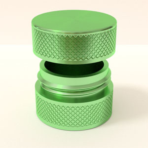
In this tutorial, you will learn how to model 3D-printable objects equipped with threaded surfaces, such as
containers with screw-on caps, bolts, nuts, etc. Specifically, the tutorial focuses on designing
a round jar with a screw-on cap that can be used to store small electronic components or fixtures.
To make things more interesting, the jar and cap feature knurled surfaces.
The tutorial is based on a calculator which spits out a Python script that generates
a threaded surface with a flattening thread profile.
Updated 2018-10-02
|
|
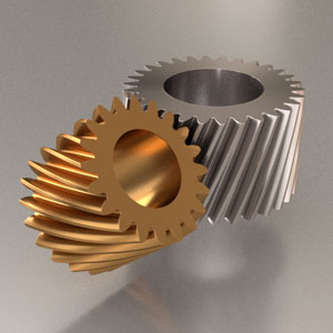
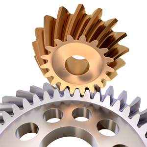
In this tutorial, you will learn how to quickly model a pair of meshing gears mounted
on non-intersecting, non-parallel shafts. These gears are known as screw gears, or crossed-helical gears.
Screw gears are typically mounted at 90° to each other, but it does not have to be that way.
Any shaft angle between 0 and 90° can be used. On this picture, the gears are mounted at 50° to each other.
The tutorial will also demonstrate how to test a pair of screw gears for compatibility using Blender's
rigid body physics engine.
Updated 2017-05-12
|
|
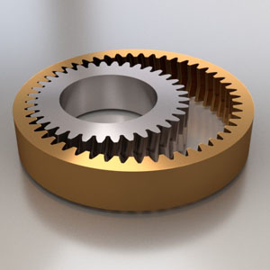
In this tutorial, you will learn how to instantly model the outlines of an internal/external gear pair in Blender
using an online calculator we have developed, and then turn these outlines into full-bodied gears and test them for compatibility
using Blender's Rigid Body Physics engine.
The tutorial will also demonstrate how to add a sun (center) gear to the system to produce a fully functional planetary
mechanism, and how to test it with the rigid body physics engine too.
Updated 2017-05-07
|
|
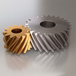
In this tutorial, you will learn how to model involute gears instantly using our brand-new online calculator.
With the help of this instant gear calculator, a pair of perfectly meshing straight, helical or herringbone gears with involute
teeth and profile shifts can be created in under 90 seconds, as demonstrated in the tutorial.
Helical gears are stronger than straight gears due to a greater load bearing surface area, but due to the curved shape of their teeth,
they are subject to an axial load. This problem can be solved with the help of herringbone gears.
A herringbone gear is essentially two helical gears with opposite hands, stacked on top of each other.
Updated 2017-05-02
|
|
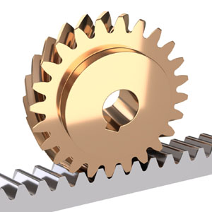
A Rack-and-Pinion refers to a gear mechanism which converts rotational motion into linear motion.
It consists of an involute gear wheel (pinion) and a mating toothed bar (rack).
The teeth of a rack-and-pinion pair can be straight or helical.
A rack-and-pinion is found in the steering mechanism of vehicles and many other places.
In this tutorial, you will learn how to design a rack-and-pinion mechanism in Blender and test
it with Blender's rigid body physics engine. Both straight-toothed and helical gears are covered.
Updated 2017-03-22
|
|
When a car turns, its driven wheels operate at different speeds as the inner wheel has to travel a shorter distance to complete the turn.
This is made possible with the help of the automotive differential, an ingenious mechanism which splits the engine's torque
between the two wheel shafts and enables one of the wheels to
revolve faster than the other when the driving conditions call for it, such as during a turn.
In this tutorial you will learn how to design an automotive differential mechanism in Blender, and also test it in both the straight-motion
and turning modes of operation using Blender's rigid body physics engine.
Updated 2017-01-30
|
|
The recently invented Eccentrically Cycloidal (EC) drive is closely related to the hypocycloid drive described in our
Tutorial #5.
From the modeling point of view, these two mechanisms are very similar as they are built around the same basic shape - the cycloid disk.
In fact, both tutorials use the same online calculator.
With the help of this calculator, designing a functional EC drive will only take a few minutes.
This tutorial also tests the EC gear pair for compatibility using Blender's Rigid Body Physics engine.
Be aware that the EC drive is covered by a number of US and international patents. This tutorial was created with the explicit
permission of the patent holder.
Updated 2016-12-16
|
|
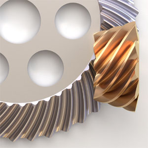
A hypoid gear drive is similar to a bevel gear drive, but the axes of the pinion and wheel
in a hypoid drive do not intersect. Hypoid gears are widely used in automotive and other industries.
They offer high gear ratios, good efficiency and
sturdiness of the assembly.
The math behind hypoid gears is daunting, but thanks to the online hypoid gear calculator we have developed, you don't need
to worry about it at all.
This concise tutorial shows you how to design your own hypoid gear pair in Blender easily.
Updated 2016-11-11
|
|
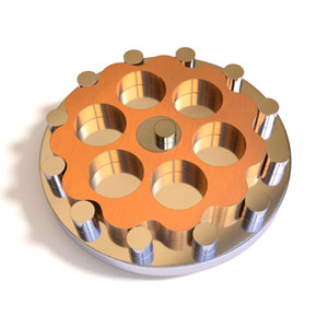
In a hypocycloid (or simply cycloid) speed reducer, a flower-shaped gear called cycloid disk moves around a stationary ring of round pins
in a cycloidal motion, driven by an eccentric bearing or cam connected to the input shaft.
Radial holes on the face of the cycloid disk in turn drive the pins of the output shaft.
Hypocycloid drives are widely used in the industry due to their excellent characteristics, such as wide range of gear ratios,
compact size, smooth transmission, high efficiency, high overload capacity, low noise, long service life,
and compact design. With the help of our tutorial, you can
design your own hypocycloid drive in Blender in a matter of minutes.
Updated 2016-10-12
|
|
The Planetary, or Epicyclic, gear mechanism consists of one or more planet gears revolving around
a central, or sun gear. Typically, the planet gears are mounted on a carrier
which itself rotates relative to the sun gear. A planetary system also incorporates an outer ring gear
which meshes with the planet gears. The teeth of the ring gear point inwards.
Gears like that are often referred to as internal.
The planet and sun gears are regular, or external, gears, and the design process for those was covered in our Tutorial #1.
However, the design of an internal/external gear pair requires its own set of formulas and
its own calculator. This tutorial covers the modeling of a profile-shifted ring/planet gear pair, and sun gear.
Updated 2016-08-16
|
|
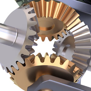
Bevel gears, also sometimes called conical gears, are gears where the axes of the two shafts
intersect and the tooth-bearing faces of the gears themselves are conically shaped.
Bevel gears are usually mounted on shafts intersecting at 90°, but can be designed to work at other angles as well.
In fact, in this tutorial we are designing a bevel gear pair with the shaft angle of 100°.
Also, the gear wheels designed in this tutorial feature curved teeth and an involute tooth profile.
At the end of the tutorial, the gears' compatibility is successfully tested with Blender's Rigid Body Physics engine.
Updated 2016-07-06
|
|
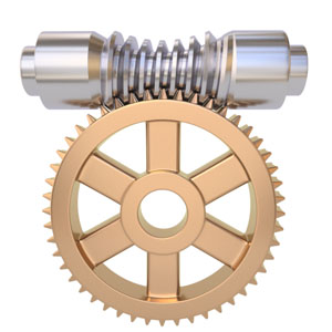
Worm drives are ubiquitous! They can be found literally everywhere, from heavy machinery to acoustic guitars.
Designing a simple cylindrical worm drive is not hard: just apply the Screw modifier to a trapezoidal tooth profile and
you get the worm, then throw in a standard involute gear wheel with slanted teeth and you are done.
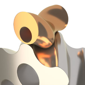
The globoid (also known as throated) worm drive is far more involved.
Its backbone is not a cylinder but an hourglass-like shape cut out of a torus.
The globoid worm screw is as beautiful as it is picky: finding a mating gear for it is not a trivial task.
In this tutorial, you will learn how to create both a worm screw and mating gear wheel in
Blender, and test their compatibility using Blender's Rigid Body Physics engine.
Updated 2016-06-10
|
|
Cogwheels are often depicted with straight and boxy teeth. However if you take a close look at
a real-world gear wheel, you will notice that the sides of its teeth are not straight at all,
and for a good reason. Two mating gears must stay in tight contact at all times, and most importantly,
the direction of pressure one gear exerts on the other must remain constant to prevent vibration and noise.
Leonhard Euler, a great mathematician of the 18th century, designed a gear profile satisfying these
requirements with the help of the involute, a mathematical curve that can be described with a pair of
simple parametric equations. In this tutorial, you will learn how to design a pair of
perfectly meshing involute gear wheels in Blender in just a few minutes.
Updated 2016-03-20
|